Anisotropic fracture of silicon wafers
The surface orientation of two broken silicon wafers was identified from their fracture patterns, the directions of the wafer flats and fracture lines were worked out with vector algebra, and the planes were checked by drawing them in VESTA.
Context
Single-crystal silicon is broken along certain crystal planes, so the way a wafer shatters says something about its orientation. In this report for the course CHEM-C2440 Materials Microstructure at Aalto, two silicon wafers, A and B, were split by striking a nail into their centres. One of them had a {111} surface and the other a {100} surface. Wafer A was broken along three directions into six pieces and wafer B along two directions into four. The task was to determine which wafer was which, and to find the crystallographic directions of the wafer flats and the fracture lines.
Approach
The surface of the {111} wafer was set as the plane (111) and the surface of the {100} wafer as (001). Silicon is typically fractured along {111} and {110} planes, and the direction of a fracture line on the surface is given by the cross product of the surface normal and the normal of the fracture plane. The unique fracture directions were calculated for both surfaces and both plane families, and the angles between them were then calculated using the dot product.
The flat, i.e. the straight edge cut into a wafer to mark its orientation, is a {110} plane perpendicular to the surface. On the (111) surface these are the planes whose dot product with [111] is zero, and (-110) was chosen, which gives a flat direction of [-1-12]. On the (001) surface (110) was chosen, giving the flat direction [100]. From the photographs, one fracture line on wafer A was seen to be perpendicular to the flat, so the direction perpendicular to [-1-12] was searched for first, followed by two directions at 60° from it. On wafer B the fracture lines were found to be parallel and perpendicular to the flat.
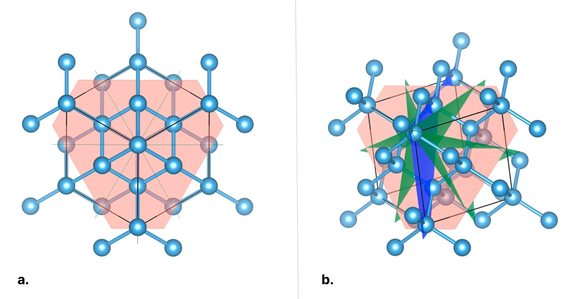
Lastly, the flat and fracture planes were drawn into the silicon crystal structure in VESTA, and the angles were checked against the photographs.
Outcome
Wafer A was identified as the {111} wafer and wafer B as the {100} wafer. On the (111) surface the fracture directions lie at multiples of 60°, which allows the six-piece break of wafer A. Its fracture directions were determined to be [-110], [-101] and [01-1], with [-110] perpendicular to the flat and none of them parallel to it. On the (001) surface the fracture directions are at 90° to each other, matching the four pieces of wafer B, and they were determined to be [100] and [010], with [100] running along the flat. The same angles were seen in the VESTA drawings.
The orientation itself could have been guessed from the number of pieces alone, since threefold symmetry is only found on the (111) surface. The more useful part of the exercise was working out the flat and fracture directions by hand, as the cross and dot products had to be applied carefully. The plane families followed by the cracks were also assumed rather than tested, so for wafer A it cannot be said from these results alone whether the cracks ran along {111} or {110} planes.